By Wagner Lipnharski
- UST Research Inc. - January 2003
Please
DO NOT COPY the text or Pictures below - Link it.
|
Baking SMT on a cheap kitchen toaster oven is not difficult. You just need some patience and exploration good will. In this page you will read the manual procedure to bake SMD boards into a regular kitchen toaster oven appliance. Follows information about how I produced an automated solution. Each toaster oven react in a different way, each one, cheap as it is, will produce a different temperature heating and cooling profile curve. Soldering SMT components to a PCB requires "some" temperature profile, that is, certain temperature for certain time, then other temperature for other time, and so on. This is NOT so much critical, as I experienced. The soldering process happens in one way or another when the everything reaches around 450°F, but critical is the sake of the components on board. Some components can crack immediately if the temperature goes up or down very fast, others don't show any damage immediately, but they will fail in a month or two (capacitors for example). As a rule, average temperature profile should be:
This cool down process is important to avoid damage to components. We need to call the attention to the fact that a cheap toaster oven, is a little piece of garbage, the thermostat is ridiculous and it is there to control temperature in a 30 minutes average, not a 2 or 4 minutes period. We need to understand how slow temperature travels from the interior of the oven to the thermostat that normally (on the cheap ovens) are located in the lateral compartment. When you set the temperature to 160°F, the thermostat is cold, so it turns on the thermal elements into the main chamber, and they got really RED. The inner temperature start to travel by the inner chamber metal plates and propagate to the thermostat at the other compartment. It can takes almost 45 seconds or more to the temperature reaches the thermostat. In 45 seconds, a RED thermal element can increase the inner chamber temperature from 100 to 300°F. So, when the thermostat senses 160°F, and turn off the thermal heaters, the temperature into the main chamber is about 350°F. In a regular cake baking or sausage roasting it does not change much the results. At this moment, the thermal elements will stay off during several minutes, until the thermostat travels from 160 to close to 350°F then back to lower than 160°F when it turn on the elements again. This process will be repeating and the cake will be ok, but not the circuit board and components. This is a very wrong profile to bake the SMT board. This mostly happens for low temperature, as the initial 4 minutes of 160°F. As a bypass to this problem, turn on the oven with the SMT boards inside for 160°F, for no more than 90 seconds, then turn it off. It will avoid the temperature to increase so much into the main chamber. If you have a way to measure the inner temperature, great, if not, just guess. Keep the boards inside and wait extra 2.5 minutes. Then turn the knob to 320°F for two minutes, turn to 450°F (full power in most toasters) for 60 to 90 seconds, turn all off. Below text and pictures about an
attempt to automate the temperature profile control, using a regular
low cost toaster oven, a solid state relay 240V @ 20A, a AVR AT90S2313
and few other electronic componts. Click here to return to the pictures of the solder paste boards and results of soldering. |

|
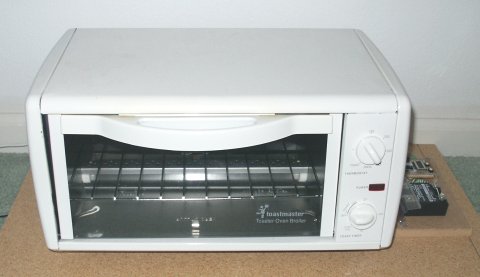
This low cost oven has the thermostat installed in the separated chamber at the right side of the oven, this causes a very long temperature lag time. At the time the thermostat senses 200°F, the inner chamber would be already around 400°F, so a long ping-pong temperature happens between the inner chamber and the thermostat, until finally it reaches some temperature stabilization with a lower ping-pong effect, but it can takes up to 20 or more minutes. I guess the chicken or the sausages would not complain, but all the SMD caps and IC's would be damaged. If means the standard installed thermostat control of this oven is NOT appropriated to solder SMD boards. Using the electronic solution presented here, increases very much the temperature control, then this toaster oven turns to be a very low cost solution. I am having a hell
of a time to find out a way to produce and install a definitive
electronic panel for this unit, since ALL covers get very hot during
the baking process. This low cost oven has no thermal
isolation between the inner chamber and the external covers, just
1/2 inch of air, at the final profile stage, the external covers
present temperature in excess of 100°C, quite dangerous.. |
|
|
|
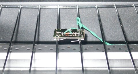
Drilled 4 corner holes, and attached the board to the grill tray using metal wires (small paper clips can do a good job). It is not very tied, so I can move the little board back or forth over the tray tick wires and position it better if necessary. The NTC leads does not make electric contact with the metal grill tray. I used high temperature 550°F wires to connect the NTC to the external electronics. The green stripped leads were just twisted around the NTC leads, solder would melt anyway. I used just a round of paper clip wire around the wire twisted around the NTC lead, just to make sure it will not unwrap in time. Even the green wires were tied to the small board using paper clip. Twisted the wires a couple of turns around the grill tray, so it will hold better. The green wires came out of the oven via al small opening on the bottom of the oven, and go to the control electronic board. The NTC operational temperature goes up to +150°C max (+302°F), according to the data sheet, I have been using it up to 450°F without any problems or damage. It already soldered more than 100 times without any change in behaviour. The data sheet does not show the resistive profile curve for 450°F of course, but using an hand held industrial thermometer I was able to draw such curve. |
|
The right side shows the experimental prototype board, with an AVR AT90S2313 microcontroller, a 2MHz resonator, a buzzer, a 7805 regulator on bottom of the board, 3 resistors, 2 capacitors, a red LED to indicate when power is being applied to the relay, two switches (Reset and Go), 9VDC DC power adapter jack, and in the middle a tinny 5 digits LCD display we sold thousands in the past. Green and White wires connecting the board to the relay, green wires going to the NTC sensor, heavy white wires serving as the power interrupt for the toaster oven. During the soldering, the oven front panel Timer is set to 10 minutes (safety procedure), Thermostat Temperature set to maximum (around 460°F), set to both thermal elements to turn on under the solid state relay control. |
|
The first learning experience, is that even with the sensor right in middle of the oven, using the same kind of material as platform, PCB material, there is always a thermal lag. It means, that when the sensor feels 200 degrees for example, and you turn off the relay and thermal elements, the whole oven temperature still increasing for some more seconds, up to 30 seconds in this oven. This happens because the thermal elements still red and hotter than the oven, so, until it cools down to the same oven temperature, it still transferring heat. This causes the turn off 200°F going between 215 to 220°F easily in 30 seconds. This is a problem, since it would always overshoot the desired temperature. To solve this, I create a pre-temperature set point. For example, to reach 160°F, the pre-temp set point is set to 140°F with 100% power control, it means, power is applied at 100% until the temp reaches 140°F, then power is completely removed from the elements. Then, the software routine waits 40 seconds. During this wait time, the oven still heating by the thermal residue of the elements. At the end of this time, the oven increased around 15 to 20°F, so it is pretty close to the desired 160°F. Then it changes the set point to the desired temperature, in this case, 160°F. At this point, the control is PWM, it means that if the temp is less than a count of 10°F (150 or less) the power is applied 100%. For each 1°F out of the desired temp (160°F) the pwm steps 10% in or out. It means that a fine temperature control takes place and then the electronics adjust 160°F in a not bad way. The same repeats for the other temperatures of the soldering profile, 325°F and 450°F. Every time a new profile temperature set point is changed, the microcontroller beeps via the buzzer, a number of beeps corresponding to the profile stage number, so just by hearing it you know what profile step is undergoing. The 450°F set point takes longer to get there. This oven has lots of thermal losses, it is not thermal isolated, and the power is only around 1100W (10A @ 110VAC) what is not good enough for a faster temperature climb to 450°F. It almost take a whole 90 seconds to go from 325°F to 450°F, and then, it would be already time to turn it off, since solder paste would be melting. Sometimes it requires extra seconds, then I changed the last profile 450°F step to stays baking for 2 minutes at this temperature. After that, the software turns off everything, waits 2 minutes for some cool down, and start to beep signaling end of solder cycle. You can then open the door and wait few more minutes before remove the boards. The following is a graph temperature data collected from an actual soldering section. The AVR collected each and I dumped from its EEPROM to Excel graph.
The vertical axis means the internal AVR temperature conversion, it means no °C of °F, but simply part of a conversion table, while horizontal axis is 5 seconds tick marks. Vertical 70 means around 160°F, while 203 means 450°F. The logging was interrupted when the profile time expired, but there is the cool down curve not showed. I never collected a better graph after that by lack of time. But it is enough to see the expected profile being followed. You can see at the horizontal tick #20 when the first pre-temp was achieved and the power was turned off. From tick #20 to #30 it was the remanecent thermal elements heat spreading into the oven, when power control resumed. The same for the second pre-temp, turned off at tick #54, it kept heating the oven until tick #64, when power control took place again. A smaller toaster oven with 4 elements, 2000W power, would give me sharper corners and faster response, but this one is doing a pretty good job, so... The AVR does not convert the readings from the NTC to actual temperature. It just convert what I need from a count from zero to 255. I produced a table about this zero to 255 range and the real temperature. The profile stored at the AVR eeprom use this zero to 255 range. It is easier to do this way, so no heavy math is needed on board. For example, in this oven, with this NTC, reading 70 means 160°F, while value of 203 means 450°F. There is not a direct relation, but the vertical axis values above is more or less Celsius degrees times 0.87. The beginning of the curve shows around 10°C and it is correct. It was collected in the garage, around December 18th when it was pretty cool in Orlando. |
|
The main idea was to build a nice panel, keyboard, 16x2 LCD display, so I could select one of 8 possible temperature profile, when soldering different components. Some components require a different temperature profile soldering. Up to now, I am soldering everything with the same profile. I am pretty sure this contraption experimental temporary prototype will be soldering board for many months now, while the definitive nice panel and assembly would stay as a nice plan only... :) The tinny LCD on board tells me the actual reading (value from zero to 255) from the NTC sensor, not that is necessary, but helps during the debug and software update. The board is powered by a wallwart 9Vdc power adapter, but the idea is to use some DRC and steal power directly from 110VAC. The current consume is low enough to allow such creepy transformerless solution. I don't like it, but for sure will be a small and low cost. For a under panel solution is could be quite safe. The AVR consumes less than 2mA at this speed, the Relay around 5mA, the LED is the power-hog, around 10mA when ON, while the buzzer consumes around 3 to 5mA when beeping. A DRC enough to supply 5V at 20mA would be ok. I need to do some experiments, but I guess a 220nF x 400V capacitor could be enough to do it.
Build a stainsteel new oven from scratch, as small as possible. Insulation and a cooling fan, driven by an external motor, long shaft and aluminum blades, so cool down can be controlled to speed. 4 x 500W heating elements, or even a coiled regular range heating element on top another on bottom. The boards slot does not need bigger than 1 inch tall, so the temperature would comes directly from the heaters, not from the surrounding environment, metals, etc. It could speed up the thermal ramps and result in a better temperature profile. Electronic board, display, keys, several profiles stored and transferred by RS232/USB or even by wireless IrDA protocol. |
|
After the solder process, the board requires an alcohol 91° wash and brush, following by hot water and soap brush to finish cleaning and removal of the extra garbage from the solder paste. 5 minutes into another warm box at 120°F will finish dry the board perfectly. The board ends up clean and shinning. If you have anything to comment or improve this page (mostly the English grammar), please contact me at wagner@ustr.net Click HERE to return to the SMT board soldering pictures. The above text and pictures are property of Wagner Lipnharski or UST Research Inc, they are not free to copy. If you want, you can link this page to your own pages, but please do not copy them. I intend to keep updating and improving this page, so copying is not smart. Linking will keep the readers with the up-to-date information. This was done with my time and dedication, just to help other people that can be wanting to do home made SMT baking. |
Last edit Feb/04/2003