|
Sony
uses
a "bit-width" codification.
This is one of the more simple code
to understand and to decode.
Lets
consider the smaller time as T, measuring 600 microseconds.
Each
transmited bit is composed by -T +T for bit zero or -T +2T for bit 1.
So,
bit zero has a length of 1200us, while bit 1 is 1800us.
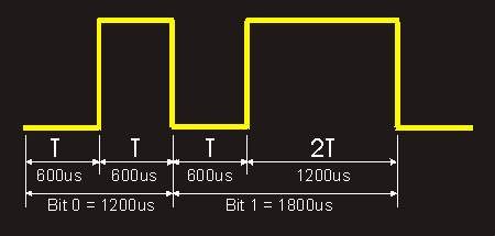
The
UP level (+T) on the above signal means infrared being transmitted
by 36kHz
carrier, while the DOWN level means silence.
If
you hook up an infrared Module Sensor, you will see this waveform
inverted
at its output, since its output goes DOWN in presence of
infrared carrier
of 36kHz.
To
save remote batteries, most manufacturers use to squeeze the UP
level time
to 5/6 and some goes up to 3/4 of the original pulse width.
By doing this,
a 500 hours battery life extends to 600 hours (5/6) or to
800 hours in the
3/4 model.
Some
other manufacturers don't care about it, and reinforce the transmit
signal
by expanding a little bit of the time the 36kHz carrier is active
It
means that in practical way, if you could scope the actual digital output
to
modulate the 36kHz carrier, based on the actual Sony Remote RM-Y123
you will
see this signal waveform.
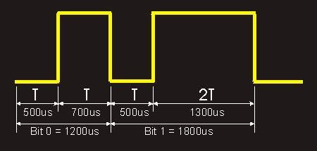
It
seems that Sony transmit 7/6 of what should be the carrier time.
Well,
lets see the frame data:
First
it is transmited a header, it can be considered a START bit.
The header has
3T width, or 1800 microseconds of active infrared.
Following
the header you will find straight 12 bits, modulated as above.
500us of Silence
+ 700us of IR for bits ZERO,
500us of Silence + 1300us of IR for bits ONE.
The
first immediate bit after the START is the LSB of the 12 bits.
Lets
name this first bit as B0, the Last will be B12.
B0 to B6 form the 7 bits
for the Command Code.
B8 to B11 form the 5 bits for the Device Address.
Some
Internet information say that Sony codification is broken down
to 3 blocks
of 4 bits, but it is not true, by doing that you can not
Identify correctly
the device model or function.
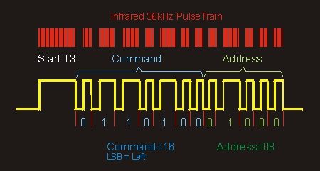
In
the above example, Address is 02, Command is 16.
There are 32 possible Addresses
and 128 possible Commands.
The
whole transmited frame, Header + 12 bits, can vary in time,
since the ONE
bits are larger than ZERO bits.
If you hold the remote button pressed,
the whole transmited frame
repeats every 25ms.
The
easiest way to decode SONY infrared, is to measure time and
locate the "1"
bits.
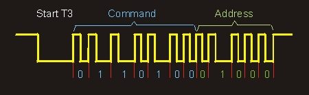
If
you use one Infrared Detector Modules available at the Market,
then all
the above waveform will be reversed as you can see below.
What is UP will
be Down and vice-versa:
The
following procedure to detect and identify the code, will work
with ANY
microcontroller / microprocessor.
1)
Set Var1 = 8, Var2 = 0
2)
Start by waiting the signal to go DOWN - This will be the START Bit (T3
time).
3)
Wait for the signal to go UP - This will be the start of the bit.
4)
Wait for the signal to go DOWN - This is the real thing, if short, bit
= 0, if long = 1.
5)
Now Wait 750 to 950 microseconds.
6)
Measure the Signal Level.
7)
If the Signal is UP - Received Bit is ZERO
-
Set Carry Bit = 0
- Rotate Right Var1 (Carry Bit enters
MSB Var1)
- Rotate Right Var2 (Var1 Carry Bit enters
MSB Var2 and Var2 bit 0 goes to Carry).
- Check Carry
Bit, if ON Goto [9], if OFF Goto [4]
8)
If the Signal is DOWN - Received Bit is ONE
-
Set Carry Bit = 1
- Rotate Right Var1 (Carry
Bit enters MSB Var1)
- Rotate Right Var2 (Var1
Carry Bit enters MSB Var2 and Var2 bit 0 goes to Carry).
-
Check Carry Bit, if ON Goto [9], if OFF Goto [3]
Observe
that here it goes back to [3] and not [4] as in [7]
This
is because if the signal still DOWN, you need to wait it goes UP,
in
[7] it is already in UP level, so it goes directly to the next step [4].
9)
Here it already read all 12 bits.
Var1
Contains 8 bits, Var2 contains 4.
The Left
5 bits of Var1 is the Address.
The Right 3
bits of Var1 + 4 Left bits of Var2 form the Command.
If
you shift right Var1 + Var2 3 times, you will have the Right 5 bits of Var1
= Address
and the Left 7 bits of Var2 = Command.
By
doing this sequence, you only need a timming routine of 750 to 950
microseconds,
and don't need to measure individual bits.
Observe
loaded VAR1 with hex 8 (binary 00001000) at entry, this bit will exit
into
Carry only after 12 times "Rotate Right VAR1 + VAR2", since it
is 4 bits on Var1
plus 8 bits of Var2 to this happen. It is
used as a Rotation Right Counter Flag.
This
is the List of Var1/Var2 read from the
SONY
Remote Control RM-Y123:
DeviceAddress
: Command Description
------------- ------- -----------
01:14
Muting
01:36
Sleep
01:15
Power
01:00
1
01:01
2
01:02
3
01:03
4
01:04
5
01:05
6
01:06
7
01:07
8
01:08
9
01:09
0
01:3A
Display
01:0B
Enter
01:0E
Ch
Guide
01:3B Jump
01:12 Volume Up
01:13
Volume
Down
01:10 Channel
Up
01:11 Channel
Down
01:16 Reset
01:74
R+
01:75
L-
01:60
Menu
01:65
Return
This
is the List of Var1/Var2 read from the
SONY
Remote Control RMT-V124B:
Device
Address : Command Description
-------------- ------- -----------
07:2A TV/VTR
07:15 Power
07:59 Tape
Return
19:76
VB (Voice Booster)
07:1D REC
07:19 Pause
07:14 x2
07:30 Direction
<||
07:31
Direction ||>
07:23 Slow
|>
07:28
Search <<
07:1A Search
>>
07:29
Play
07:1B
REW <|<|
07:1C FF
|>|>
07:18
STOP
If
you want to have your Sony remote control read and posted here, send it to our
mail address
posted at the home page. If you want your remote back, please
send $3.95 in stamps along with
the remote, so we'll ship it back to you
via priority mail (don't forget to include your name and mail
address).
If you have a list of your Sony remote control codes just email me it,
I will post it here..
Wagner
Lipnharski - UST Research Inc - March/2002
|