| STARTing everythING |
There are two ways to communicate easily with any 8051 family member, by parallel, and by serial modes. We can say parallel only when it flows 8 bits of data at once, and serial means that data flows in a stream of bits, with a synchronous clock or just using the traditional "start-stop" asynch fashion.
There are other modes with a mix of serial and parallel, as sending 4 bits twice. Some people use it with LCD's to save 4 port pins, but in this case we will consider it as semi-parallel.
Except if your microcontroller has lots of pins available (pins not in use at the board) and you like to deal with a flat cable with large wire count over the bench, the serial mode is always a pleasure, because the tiny cable with few wires and allow you to connect it at the serial or parallel PC ports.
The PC parallel port can be used to flow serial data, but it will needs a special PC software to take care of it, well, anything needs a special software. The actual speed to travel serial data, at the Parallel or Serial PC ports, is enough to any microcontroller speed. I dont see so many microcontroller applications requiring very-fast-super-high-speed, what would ask for a full 8 bits parallel data transfer.
By this
statements, we will play more with serial communications, connecting it
to the PC Serial, Parallel, Keyboard or Mouse ports. Some example
of full parallel will be presented, in real we will start with.
THE 8051 and the PC SIDE
The microcontroller side is used as:
Data Collection or Data Input
Data Show or Data Output
Device Control, as relays, leds or motors
Portable data transport, using non-volatile memory
The PC side is used as:
Permanent Data Storage
Large Data Processing and Complex simulations
Interface to other centers, via Internet or other.
MICROCONTROLLER
DATA COLLECTION OR DATA INPUT:
This
situation exist when you develop a board to collect information where a
PC can't be installed by several reasons, cost, site, size, power consume
and so on. We can think about Temperature, Voltage, Air Flow,
Presence, Liquid Flow, Movement, Pressure, Humidity, Rain, Sun, Light,
Noise, EMI, Level, Weigth, Color, Size, Reflectiveness, Impedance and so
many other applications, where a microcontroller can be used to collect
data and store for post-processing at a PC application.
MICROCONTROLLER
DATA OUTPUT OR DEVICE CONTROL:
Used
as an interface to control Lamps, Doors, Alarms, Heaters, Water Flow, Motors,
Fans, Power other devices, Speech, Sound, and so many other situations
where a cheap board can do a lot of inteligent work, where a PC would be
an expensive solution.
PC AS LARGE DATA
PROCESSING AND COMPLEX SIMULATIONS:
When
some data needs large processing, as tables, ploting, interpolation, complex
calculations and matrix data comparison, where large amount of memory is
necessary along with other large files to be used as comparison or being
part of the processing. In this situations, a PC is 100% necessary
and it would be much less expensive than develop the same processing at
a microcontroller board level.
One good example, is what you already do, use a PC to create the microcontroller program. You use an editor assembler at your PC, because it is cheapper and easy to use than try to develop something similar at a microcontroller board level, it would be at least crazy.
So, if
you use a microcontroller board to collect and log temperature, as example,
and you need to print a report about the temperature statistics, you can
develop a microcontroller program to format the printer output and print
it directly to a centronics printer port, it will works. But, if
you need a laser style printout with graphics and different character fonts,
forget it and just dump the collected data to a PC and use any cheap windows
program to do it.
WHAT WE ALREADY HAVE?
A PC has printer ports; each with 5 address port, two for output and 3 for input. The printer port can be controlled directly from ANY PC program, if you fool it to "think" your microcontroller board connected is just a printer. Suppose we connect the uC board at the PC LPT2 port.
So, you can configure your Windows LPT2 to have a regular old dot matrix printer as the "LX800", and command your programs to print as "text", not graphics. If you intend tol work in pure DOS, don't worry about nothing, it will works much better.
Wanting
to transfer some data to the uC board, just "print" it to the LPT2.
The PC will send the first byte, will flip the DB25 pin #1 "Strobe" to
signal the "printer" that there is a byte available at the port, and will
wait until the printer signals back with the "acknoledgement", pulsing
DB25 pin #10.
Then
the PC will post another byte, and it goes again until the file ends or
for some reason the PC decide that there is some error at the port, because
it checks other input pins at the printer port, as "paper end" and
"error". The "busy" bit can make the PC holds the transmission
for some time.
By this way, the transfer from the PC to the uC board is quite simple, if using the Full Parallel data transfer, requiring 8 uC port pins, plus two or three for the data flow control.
There is nothing "native" at the DOS or Windows to input data from the Parallel port, to be used easily.
At the mouse and keyboard ports the story is different. We already have the PC reading the Keyboard all the time, and it can control jobs, batch files, run programs and so on. So, a uC board connected to the PC keyboard port, simulating a keyboard, is something interesting and can make the imagination fly high. Simulate a mouse can be interesting for some graphic application, where the uC board can plot graphics and draw figures based on the collected data, or "real-time" interface to what the uC is receiving from the external world, as temperature, voltage, sound, an so on.
The only "native" DOS programs that can use the Serial port is the "COPY" command. Typing "COPY /B filename.ext COM2:" will make the BIOS try to open the port and send the contents of that file to that port, in the speed and mode previously programmed. The same happens to the printer port when issuing "COPY /B filename.ext LPT2:". The "/B" option makes it copy the file literaly, without any character translation, it means a "binary copy", so a character hexa "1A" in the middle of the file will means just a character to be send and not meaning "end of file" as usual.
Well, we have something, but it is not much. We need to create a program that allow us to interface better the uC board to the PC. It needs to do:
1) Open a PC file and send its contents in Serial way to LPT1, 2,
3 or COM1, 2, 3 or 4.
2) Receive data from LPT1, 2, 3 or COM1, 2, 3 or 4 and record it
in a PC file.
3) Understand control characters sent by the uC board.
4) Send control characters to the uC board.
5) Understand parameters passed to it, as number of bytes to transmit,
speed and so on.
6) Understand and deal with port Interrupts, so the uC board can
initiate something new.
7) Being able to check the validity of the data received, as well
transmitted, using some CRC code.
8) Being funny, easy to use, small, and functional.
All of the above can be done in a single PC program, controlled by a program screen or by simple "command line" parameters, what I think is best since you can do it via a batch (.BAT) file.
As everything, we need standards, we don't have any, so we need to state some:
DATA is defined to be what flows in the interface, and it can be represented by 8 bits, in 256 combinations, so, anything ca be considered "DATA".
DATA Interface is defined to be the "main" 8 data pins, that carry the DATA itself.
CONTROL
is defined to be
what controls the other side, and it can be represented by 8 bits, in also
256 combinations. It is also a data, but it needs a special flag
to tell the other side it is a Control.
Control
can be used for many situations, to means something special, like "end
of file", "start of new data block", "next two bytes is block size", "disconnect",
"next byte define new communication speed", "next 8 bytes is the data block
name", "next 12 bytes is the file name.ext", "beep", "sing", "jump", "seat",
"stay", "roll"... :)
(Control ) FLAG is defined to be a special situation where the other side understand something is different at the data interface, like when you press the "Shift" or "Ctrl" key at your keyboard, in our case it will tell the other side the byte at the data interface is a CONTROL.
COMMAND
is defined to be what the PC can receive from the uC board
and needs to repass to its operational system, as if it was issued by the
PC keyboard. Example; The uC board can issue a command
"DIR" to check the existent of some special file at the PC hard disk, as
it is expected to be downloaded, or issue a "COPY /B filename.ext LPT2:"
to receive that file. A Command can be issued using a special
Control defined to do it. We can select any Control byte to
define a "Command" follows, like for example, hex CC, it will means the
next bytes will be a PC command to be executed, while the command line
will be ended by a character hex 0D (decimal 13) "Carriage Return" and
a hex 00 (zero). Then, for example the Command "DIR" would
be: ...... [CC] 44 49 52
0d 00.
The
[ ] means that at the CC time, the Control Flag was active.
DATA
FLOW CONTROL is defined
to be exactly what tells the other side that this side already put a byte
at the Data Interface, and that the other side can read it as a "valid
data". The other side needs to confirm the reception of that byte,
so this side can put another byte, and so on. It also can tell which
side has the right to put bytes on the data interface, and be the
"sender".
Explaining abount "FLAG"
(Control) Flag can be generated by two ways; Hardware or Software.
By hardware it needs the use of a special port pin, than when activated it means to the other side that the byte at the data interface is in real a Control byte, not a simple Data byte.
By software is a little more complicated, it needs to have a preceeding sequency of bytes, as a "key" to the other side understand that right after the "key sequence" follows the Control byte. Some softwares use the character hex 1B (decimal 27), ESC key, as the key to means the next byte is a Control byte, but, what if you need to send a real data byte with the contents of hex 1B ? Then you need to use another kind of "key", that means "transparency", some softwares use the character hex 10 as the key to the 1B. It means that if you send 10 1B, the receiver needs to understand that 1B is a data byte not a key for the next byte being a Control byte.
What is the chances you need to send exactly this combination 10 1B as data bytes? Exactly one in 65536. Ok, it is not good, so they created the transparency of the transparency, it means, if you need to send exactly the combination 10 1B as data bytes you need to tell the other side it is not key characters but simple data bytes, using 10 1B again in front of it, so, if the receiver sees 10 1B 10 1B, it will means just the second 10 1B are data bytes. Confuse? yes, it is. The receive needs to keep track of the last byte received and if the last two were 10 1B, it means the next is just data byte, except if this next byte would be a 10 and the next a 1B.
What
are the chances you need to send the following sequence as pure data bytes:
10 1B 10 1B ?
Doesn't
matter, just insert 10 1B in front of every combination 10 1B, so the final
transmition will be 10 1B
10 1B 10
1B 10 1B
(red bytes are the transparency for the blue bytes).
There
is another possibility, use any combination for Control Bytes, but never
1B, so, if you need to send hex 1B as a Data Byte, just insert another
1B (flag) in front of it. The receive will understand that a "Control
1B" ( 1B 1B ) means character Data 1B. It is lots easier
than use the "transparency" trick above. By this way you can have
only 255 different controls, not 256 anymore, and trust me, still a lot.
Then,
to fix the idea, everytime the receiver sees a character hex 1B
(flag), it will consider the next
byte a Control
Byte, except
if that next byte is also 1B,
then it will consider it a Data
Byte.
In this
fashion, to send a series of 5 x 1B DATA bytes, just send 10 x 1B.
Complementing
the text above about send the "DIR" command to the PC, it would be hex:
1b
CC 44 49 52 0d 00, meaning:
1b ( Flag ),
CC ( control = command ),
44 ( D )
49 ( I )
52 ( R ) ,
0d ( Carriage Return ) and
00 ( Zero ) to end the command sequence.
The PC then would understand that it needs to issue a DIR command to the DOS. For sure it would only print the DIR text at the PC screen, without any usage for the uC board, but the command could be "DIR *.* > DIR.TXT", so the Dir command would copy the result to a file name "DIR.TXT", so later the uC board could ask the PC to transmit that file to it for proper usage.
Hardware Flag is a little bit easier to use, but it requires an extra port pin and an extra wire at the cable. Is that a problem? We have plenty of pins at both sides, except for the Keyboard.
We will go for a sofware flag, so it can be used in a simple two wire (plus ground) communication in the SERIAL fashion, or a regular 8 data pins + clock (and ground) in the PARALLEL way.
Talking
about "SYNCHRONIZATION"
Data
synchronization is very important, as much as when you talk at the phone,
somebody else needs to be at the other phone at the same time, not before,
not later, if not, you will not transmit the message. Even the "beep"
from the answering machine is a synchronization method to tell you when
to start to talk.
We can use few ways to tell the other side our data byte is ready to be "sampled",
1) Pulsing
some pin on the interface, what requires another cable wire and an extra
port pin.
2) Use
some electric protocol to be followed when using a single wire for serial
data transmission.
The first
case is mostly used in the Parallel way, when the sender side just pulse
a port pin. In the PC printer parallel port, that line is known as "Strobe".
When the PC post a data byte to the printer, it pulse the "strobe"
pin #1 on the printer cable, so the printer is "advised" to get that byte.
When the printer gets that byte and it is ready to receive the next, it
pulses another port pin, the "acknoledgement", so the PC knows the printer
received the previous byte and it is ready for the next.
In some
way it is a waste of pins, since they could share just one port pin pulled
up by the PC when the data is ready and shorted ground by the printer when
it accepted the data, so the PC could understand it, but, they had their
reasons to do the way they did it.
The second case is used when communication channels doesn't allow more than just one channel (port pin) to transmit and another to receive. This is a typical case of a modem communication, so everything needs to go via the single channel, including synchronization. Another case is when using long distance cables, that would cost more to have multiple wires, local-area-networks and coax-cables terminals like IBM 3270 and others. They flow bidirectional data in both ways in the same single wire coax cable.
Even that a PC serial (COMx:) port has several pins at the DB25 or DB9 connector, it uses just one for data TX and another for data RX. The other wires (circuits) are just interface between the modem and the PC, and have little to do with the data itself. We can call them as part of the "physical protocol".
In the SERIAL way, without any further synchronization, actually the most common is the asynch PC ports, known as "Start-Stop", "Asynch" and other names, it doesn't matter the name, the electric protocol is always the same.
First, both sides need to establish a common communication speed, and this is why you need to set the PC COMx: port to 1200, 2400, 9600, and so on, before operate it. This is also one of the reasons the modems "scream" right after the phone connection, they are exchanging communication capabilities of each one and also "testing" the phone line to see how they will operate in the sequence, as, error correction, speed, modulation, top speed, auto-speed reduction, and so on. It is the same thing you did at the first days at school... knowning your pairs... and learning how to deal with them.
Back
to the RS232 interface, and forget modems for a while, think about a PC
and a microcontroller connected directly via a serial cable.
CLOCK SIGNAL
Data bit
0 1 0 1 0 1 0 1 0
1
___---___---___---___---___---
Clock signal i i i
i i i i i i i
In the above example, the clock signal "i" if transmited with the data bits to the receiver, could tell it exactly "when" it could sample the Data bit wire, to get it right, not before, not after. This is important, since during the transition time from zero to one, and from one to zero, it can happens a noise thing, unstable voltage on the Data wire. If the receiver sample the wire during that "noisy time", it can read something different from what was sent. So, the idea to sample the Data pin exactly in the middle of the "data bit time", we can call it "the gate time" is something that the receiver must "try" to obey. This is why the "i" (clock) pulse needs to be exactly in the middle of the data bit.
What happens when we can't send the Clock Signal along with the Data bits...? The other side needs to have an "idea" of when is the "gate time"... but how? Again, synchronization is the word, if both sides use the same clock speed, if the string of bits is send in a perfect sequence in time, and if the sender can tell the receiver "when" the first bit starts, then the receiver can do a half bit delay (time to reach the middle of the first data bit - the "gate time") and then starts to sample the Data bit wire at where the receiver suppose is the gate time, and most of the time it is. So, both sides need also to know how many bits will be transfered, so the receiver will know when to stop to sample, and also if there will be a parity bit, kind of 50% chance to find a reception error.
Well, so that's ok. Now, we stablish that there is only two states on the RS232 TX data bit, ON and OFF, what means "MARK" (-4 to -15Vdc) and "SPACE" (+4 to +15Vdc), so, an idle line will be in Space condition. When the sender wants to initiate a byte transmission it needs to signal the receiver when this will start, it changes the line voltage to the MARK condition, and will hold that level for a whole bit time, so it will be an extra bit in front of the real data byte. By this way, the receiver will be alerted that a sequence of bits started. The receiver will sample this first MARK bit (we can call it START bit) for a whole bit time to ensure it stays in the MARK state and then understand this was the START bit, and that the sequence of bits will follow it in the pre-programmed speed.
In the RS232, the first bit to be transmited is the lowest bit in the byte (LSB), bit zero, followed by the bit 1, 2, 3, 4, 5, 6, 7 then the sender change the TX line level to SPACE, for 1, 1½, or 2 bit time, according with the previously defined between both parts, and it is called STOP bit. After the reception of the predefined quantity of bits per byte (7 or 8), the receiver will check the Data pin level, it must find the STOP bit (SPACE level), if not, something is wrong and it can signal some kind of error, we can say it was a 'Frame error', since it should be in Space level.
The pre-definition about 1, 1½ or 2 STOP bits, is just to allow the receiver some time to do something with the byte received. In case it is a paper-punch machine, or a mechanical printer, it needs some time to do the job, before be able to receive the next byte. Some old machines took time to do the mechanical job. My first printer was a Teletype 33, it use to print at the top speed of 120 bps, what is something around 10 cps (characters per second), pretty fast for all the mechanical involved.
The stop bit quantity doesn't change nothing in the Data wire, just a way to define how long the transmitter will wait before send the START bit again for the next byte. For sure the second STOP bits will increase in aprox 10% the time needed to send a byte, so the use of only 1 STOP bit is the best.
Now, lets see, to send a byte with 8 bits, we have;
1 START BIT
8 DATA BITS
1 STOP BIT
___
____ space
|___|XXX|XXX|XXX|XXX|XXX|XXX|XXX|XXX|
mark
start 0
1 2 3 4 5 6
7 stop
So, we have 10 bits to send just 8. This extra 20% of time is necessary to avoid the extra wire and port pin to send the CLOCK signal.
There are other ways to send data without the Start and Stop bits, this is called Synchronous Communication, as in the IBM BSC-1, BSC-3, SDLC, HDLC and so on, but it is not our job here.
The Start-Stop
way, allow the sender to wait anytime it wants between bytes, it doesn't
need to start the following START
bit (to send the next byte) right after the end of the previous byte STOP
bit.
It can
wait 5 minutes, if the receiver would wait for it, even two days. :)
The internal microcontroller UART can do all this job to insert the Start and Stop bits, and send all the Data byte bits in sequence, starting by the LSB, according with the clock speed defined previously.
CLOCK SPEED
In real, the clock speed can be literally ANYTHING, it can be 1735bps, or 11980bps, but it would be difficult to both sides define and generate that clock rate. This is why some standard rates were defined, as starting in 134.5, 300, 600, 1200, 2400, 4800, 9600, 12000, 14400, 19200, 24000, 28800, 48000, 56000, 57600, 64000, and so on. Later on, some intermediate frequencies were defined by inteligent modems that can locate the best speed for phone lines, in between 24k and 28k, as 26400 for example.
In our case, we can deal with traditional speeds as 2400, 9600 or 19200. We really don't need higher than that for our little study here.
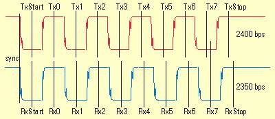
The communication speed at both sides doesn't need to have an atomic controller clock, it can take some variations from one to another, but never more than 3%. It means that one side can have a transmission clock at 2400Hz and another with a variation of ±96 Hz (2328 - 2472Hz). To understand that, suppose the sender is at 2400 Hz and the receiver at 2350 Hz, for the sender the "bit time" would be exactly 416.6us, while for the receiver it would be 425.5us. At the START bit, both would get "perfectly" synchronized, but the 10th bit gate time would be at 3.9577ms for the transmitter and 4.04225ms for the receiver, with a difference of only 84.55us. The receiver needs to sample data bit at the middle of the bit, the gate time, but if it sample it a little bit early or late, inside the bit time, it still working. Counting from the START bit, the one that synchronized the byte, the transmitter 10th bit has the duration from 3.7494ms until 4.166ms, then, the receiver sampled it at 4.04225ms, just 2.1% out of the sync. This kind of error is cumulative until the next synchronization, that will occour at the START bit of the next byte to be transmitted. So, the problem is not that big.
The next
graph shows a 10% error, what is not acceptable, since at the receiver's
bit 4 gate, it is already sampling the begining of transmitter's bit 5.
The second graph is imaginary, since the receiver sees the same as it is
transmited, but the bit gate defined by the lower "i" show you the slack
error. You can think as the second graph is what the receiver is
expecting to receive with its lower clock (2160Hz). Both graphs shows a
transmission of a byte hex AAh. Remember, at the RS232, the levels
are inverted, bit 1 means low voltage, and the lower significant bit (0)
is transmitted first.
======+ START +--------+
1 +--------+ 3 +--------+
5 +--------+ 7 +--------+=======
2400BPS
TX |________|
0 |________| 2 |________|
4 |________| 6 |________|
STOP
! !
! !
! !
! !
! !
======+ START +---------+
1 +---------+ 3 +---------+
5 +---------+ 7 +--------+=======
RX |_________|
0 |_________| 2 |_________|
4 |_________| 6 |_________|
STOP 2160Hz
i i
i i
i i
i i
i i
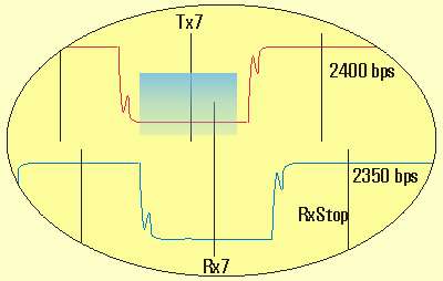
The following
graph shows a 2.1% of error, what is totally aceptable:
The following graph shows a zoomed section of the 9th bit sent, showing both the Tx and Rx bit gate time, while you can see that both gates fall in the blue acceptable region.
Because this permissible "clock slack", lots of communication devices around don't even use a crystal to fix the communication speed, sometimes a stable RC oscillator can works nice. I already saw some Caller ID units using a simple TTL oscilator with a small trimpot to adjust the frequency... strange, since the pot cost almost the same as a ressonator... well, at that scale, every cent counts, this is why they can sell Caller ID Units for 8 or 9 dollars.
What means that? Suppose one microcontroller crystal is exactly 6MHz, and the baud rate (communication clock) is a division of that clock. Now, the other side can have a 2.1% of error in its crystal frequency, something in between 5.874MHz - 6.126MHz, and both might work fine with the same code that generates the division for the baud rate. The regular crystals you can buy at Digikey or other, gives you 50ppm, or 50 parts of error per million of the "thing", so it is 50/1000000 of frequency deviation, or 300Hz for a 6MHz crystal. This is something around 0.005% of error, pretty good for our communication study here. We don't need to worry about that. Note that normally "ppm" means "part per million per Celsius degree" that the unit change with temperature. Here they use as "possible deviation". Even thinking ppm as temperature variation changing frequency, the crystals above have a frequency difference of 126000 Hz, what means 126000/50 = 2520 Celsius Degrees in one crystal to reach that difference (impossible, but suppose it was possible, they would still working).
Ok, now you know
about:
Clock, Clock Deviation, ppm, Synchronization,
Flags, Control Flags, Commands, Parallel, Serial,
DataFlow Control, RS232 levels, Start-Stop,
why 2 stop bits (is not everyone that knows that),
and more.
Now, you can return
to the previous screen, and select the subject of your choice,
Parallel, RS232, Mouse,
Keyboard or any other I already put there.
http://www.doc.ic.ac.uk/~ih/doc/par/doc/regpins.html lscgid: execve():/home/sanckvet/public_html/ustr/cgi-bin/ax.pl: Permission denied